PLC
What is a PLC?
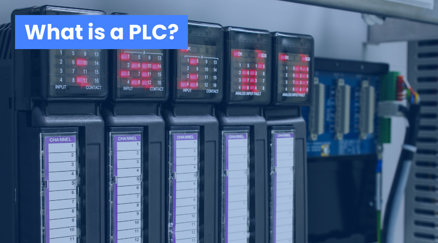
PLC stands for “Programmable Logic Controller”. It is an electronic device used to control machines and industrial processes.

Ladder Language is a graphical language used to program Programmable Logic Controllers (PLCs), electronic devices used to automate processes…
 Filippo MaselliControl and Automation Engineer
4 min read
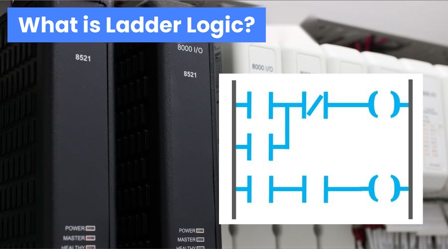
Ladder Language is a graphical language used to program Programmable Logic Controllers (PLCs), which are electronic devices used to automate industrial processes.
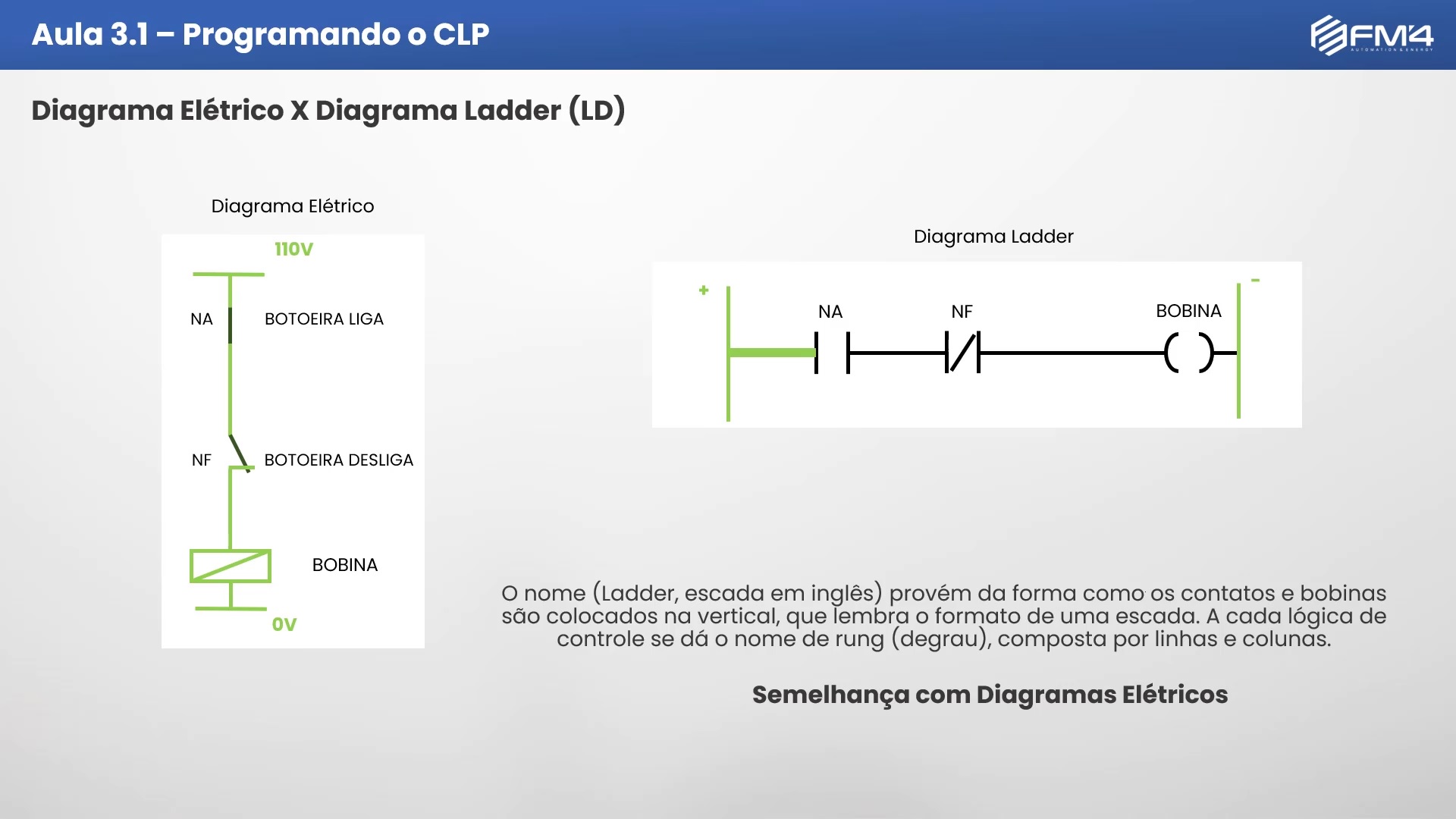
Ladder Language is based on electrical diagrams, which were used to build relay circuits that drove machines and equipment, such as hydraulic cylinders and electric motors. All electrical circuit devices, such as push buttons, valves and solenoids, can be represented as symbols in Ladder diagrams, including their connections.
Ladder Language was the first programming language developed for PLCs. Since PLCs were created to replace relay logic control systems, it was only natural for Ladder Language to resemble the diagrams used to document relay logic. As a result, engineers and technicians who were already familiar with relay logic did not need extensive training to understand or develop a Ladder program.
Ladder Language is one of the five PLC programming languages defined by the IEC 61131-3 standard, which standardizes PLC concepts and features. The other four languages are: FBD (Function Block Diagram), ST (Structured Text), IL (Instruction List) and SFC (Sequential Function Chart).
The name Ladder comes from the fact that the symbols are generally laid out vertically, resembling the shape of a ladder. Each piece of control logic is called a rung, made up of rows and columns. To learn more, check out our PLC Programmer Course by clicking here.
Ladder Language works through a scan cycle performed by the PLC's processor (CPU). The scan cycle consists of the following steps:
The scan cycle runs continuously and quickly, so the results at the outputs are almost immediate. The scan time depends on the complexity of the program, the number of inputs and outputs, and the capacity of the PLC. The shorter the scan time, the greater the accuracy and reliability of the control.
To program PLCs with Ladder Language, you need specific programming software, which can vary according to the PLC manufacturer and model. The programming software lets the programmer create, edit, test and download the Ladder program to the PLC, as well as monitor and debug how the program runs.
Ladder Language is made up of two types of symbols: contacts and coils. Contacts represent the PLC inputs, which can be sensors, push buttons, switches, etc. Coils represent the PLC outputs, which can be actuators, lamps, relays, etc. Contacts and coils can be of two types: normally open (NO) or normally closed (NC). NO contacts and coils are represented by a horizontal line, while NC contacts and coils are represented by a horizontal line with a diagonal.
Contacts and coils are connected by vertical and horizontal lines, forming the rungs. Each rung represents a logical condition that must be met for the coil to be energized. The vertical line on the left represents the PLC's power supply, which provides the voltage needed for the circuit to work. The vertical line on the right represents the power return, which closes the circuit. The upper horizontal line represents the positive bus, while the lower horizontal line represents the negative bus.
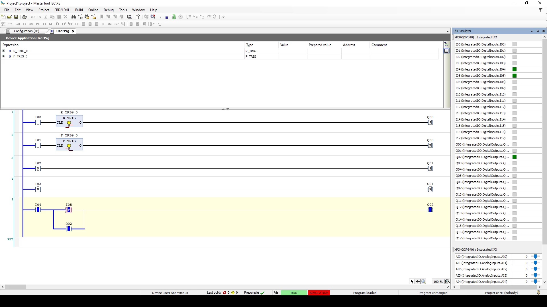
Contacts and coils can be combined in series or in parallel, forming more complex logical expressions. A series connection represents a logical AND operation, meaning that all contacts must be closed for the coil to be energized. A parallel connection represents a logical OR operation, meaning that at least one of the contacts must be closed for the coil to be energized.
In addition to contacts and coils, Ladder Language also has other symbols that represent special functions, such as timers, counters, comparators, math operations, etc. These symbols are called function blocks, and they can have input and output parameters that are configured by the programmer. Function blocks can be combined with contacts and coils to form more sophisticated rungs.
Ladder Language is a graphical language used to program PLCs, which are devices used to automate industrial, residential or IoT processes. Ladder Language is based on electrical diagrams, which were used to build relay circuits that drove machines and equipment. Ladder Language works through a scan cycle performed by the PLC's processor. Ladder Language is made up of contacts and coils, which represent the PLC's inputs and outputs, and function blocks, which represent special functions.
// keep reading
PLC stands for “Programmable Logic Controller”. It is an electronic device used to control machines and industrial processes.
PLC stands for Programmable Logic Controller, an electronic device used to automate industrial and residential processes…
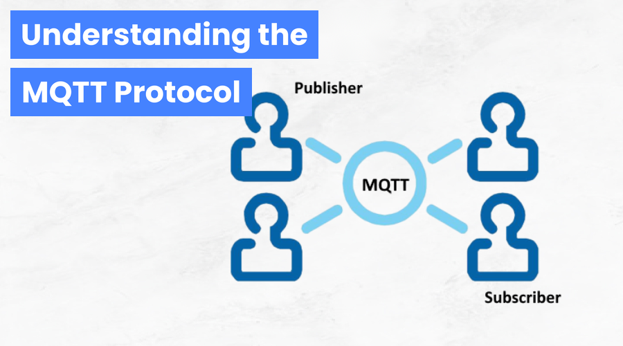
Find out what the MQTT protocol is, how the publish/subscribe model works and why it is essential for IoT and industrial automation in Industry 4.0.
// from article to practice
In FM4 courses you program PLCs and SCADA systems hands-on, with step-by-step lessons and instructor support.